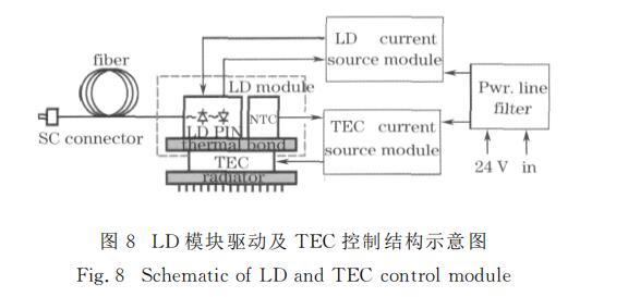
According to different use conditions, the temperature control of the LD module can adopt cooling methods such as water cooling and air cooling. In this paper, the semiconductor refrigeration (TEC) temperature control working mode is adopted, which has the advantages of small size and low power consumption. Figure 8 is a schematic diagram of the LD drive module and TEC control structure. It is mainly composed of LD chipset, chip carrier, PIN back-monitoring photodiode, TEC thermoelectric device, NTC platinum resistance temperature sensor, LD drive laser current source module, TEC temperature control current source module, etc., Pwr. The line filter is an electromagnetic compatibility filter.
The schematic diagram of the TE module temperature control circuit of the LED module in Figure 8 is shown in Figure 9. A platinum resistor Rt with a positive temperature coefficient is attached to the surface of the chip carrier. A CC4 mA constant current source provides a DC bias for the platinum resistor temperature measurement. The current source is a small current constant current source composed of an operational amplifier. By detecting the DC voltage across the platinum resistor, the temperature and temperature change rate of the LD module are calculated to determine the use of different TEC drive currents under different environmental conditions to achieve The purpose of optimizing (or nearing optimal) temperature control.
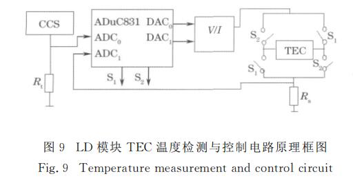
V / I conversion circuit composed of DC / DC conversion, etc., whose output current is proportional to the control voltage, provides driving current for TEC, and its output current is controlled by the DC voltage output from the DAC0 port of the ADUC8311 single-chip microcomputer. The current is between 0 and 5 A. Continuously controllable. The DC voltage output from the DAC1 port is used to control the on / off of the V / I conversion circuit to complete the power protection function. The switches S and S in the converter bridge circuit consist of non-contact switches with MOS field effect transistors with extremely low on-resistance. The two I / O ports of the microcontroller control the on and off of the switches S1 and S2. Simultaneously turn on, make S1 and S2 have the interlock function in the circuit design. The cooling or heating mode is changed by changing the direction of the current flowing through the TEC. In the figure, Rs is the TEC working current detection sampling resistor, and the working current flowing through the TEC is calculated by detecting the voltage across it.